
Selecting the Right Cable Cleat: A Complete Guide
February 18.2026
Selecting the right cable cleat is one of the most important steps in designing or installing a reliable power distribution system. In data centers, Uninterruptible Power Supply (UPS) paths and other industrial electrical environments, cable cleats are the critical components that prevent a brief short circuit event from turning into major damage to cables or equipment. When a fault occurs, magnetic forces between conductors rise causing cables to fly apart in an explosion like event that can damage equipment and injure staff. A proper cleat keeps cables contained, so the system stays safe and your project stays on schedule.
Even with their importance, choosing a cleat can feel complicated. Engineers have to balance fault-current levels, cable size, tray/ladder geometry, available working room and code requirements while simultaneously trying to avoid overengineering and installation friction. Standards such as IEC 61914, which describes how cleats are mechanically tested, and NEC Article 392, which outlines requirements for securing conductors in tray systems, provide the framework, but they don’t simplify day-to-day decisions teams face in the field.
This guide breaks the process into practical steps that can be used on any project. It explains which variables matter during a short circuit event, how to evaluate, and then select a cleat based on the applications environment and installation restraints.
Fault Current Potential & Why it Drives Cleat Selection
Short-circuit events generate strong electromechanical forces between conductors. The cleat must be able to hold cables in place during these brief but critical moments in order to avoid an explosion that can lead to injury or damage equipment. IEC 61914:2021 defines how cleats are tested against short circuit forces and the key factors that affect those forces, such as peak fault current, cable spacing, and cable arrangement.

Annex B shows how these forces are calculated and why different layouts, like trefoil versus flat, experience different levels of stress. It also highlights how cable diameter and distance between cleats change the load each cleat must hold. Understanding these points helps narrow down which cleat types can handle the systems worst case short circuit conditions.
Key Variables Identified in IEC 61914 Annex B:
- Peak Short Circuit Current: The highest instantaneous current drives the magnetic forces between conductors.
- Cable Spacing and Formation: Trefoil and flat configurations create different electromagnetic interactions and therefore different force profiles.
- Conductor or Cable Diameter: Diameter affects the physical spacing between phases, which is part of the force calculation.
- Cleat Spacing: IEC 61914 requires manufacturers to declare the maximum spacing used during testing. Cleat spacing also determines how much force individual cleats must restrain.
IEC 61914 gives the basic formulas for figuring out these forces.
Annex B also includes estimates for the forces in trefoil and flat three phase formations, often used in LV, MV, and HV power distribution. These estimates help designers predict the maximum forces and choose a cleat that can handle them.
|
LV vs MV/HV: Why It Matters for Cable Cleats IEC 61914 classifies LV cables as those rated 1.0 kV AC or below, or 1.5 kV DC or below. Anything above those levels is treated as MV/HV for short circuit testing. MV and HV are grouped together in the standard because once you move past LV, you need different test cables and high force evaluations. In real world applications, MV and HV circuits can generate much higher fault forces. That means the strength of the cleat, how far apart the cleats are installed, and how well they hold the cable in place become far more critical. |
Key Factors That Drive Cleat Selection
1. Typical Short Circuit Ranges
- Up to 76kA: Where medium composite, aluminum, polymeric, or coated band cleats are typically used.
- Greater than 76kA and up to 120kA: Where high retention stainless-steel or reinforced systems are required.
- Above 120kA: Where heavy mechanical stainless-steel assemblies are specified.
2. Diameter Adjustability
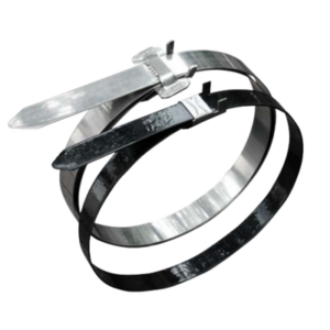
Correct sizing is essential. Cleats need to match the cables outside diameter and formation. BAND-IT’s coated and uncoated BAND-FAST® Cable Cleats accommodate trefoil bundles up to roughly 70mm, reducing the number or SKUs compared to bolt style cleats that are sold in narrow diameter increments.
|
Why Banding Dramatically Reduces SKU Count Across three leading cleat manufacturers, a single 120kA BAND-FAST cleat (LFEC-F123-M120) covers an average of approximately 67 SKUs that fall within ≤70 mm diameter and tested short circuit rating envelope. |
3. Tray or Ladder Rung Geometry
Your tray or ladder choice affects which cleats can be used and how easily they can be installed. Rung spacing, slot dimension, underside access, and cleat spacing are all essential. Under NEC Article 392, conductors must be secured to the tray, and these requirements are especially important on non-horizontal runs. Bolt style cleats rely on accessible mounting points and proper torque. BAND-FAST, on the other hand, feeds directly through the rung slots and adapts to several tray geometries.
4. Installation Workspace
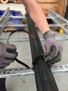
Bolt-style cleats usually require you to lift the cable into the cleat or reach under the tray rung to tighten the bolts. This can be tough in overhead, mezzanine, or underfloor areas. BAND-FAST makes this process easier because it wraps around the cable and the rung after the cable is pulled. It doesn’t require access from underneath or any prestaging, which cuts down on labor and makes routing simpler.
5. Environment and Code Requirements
Cleats must tolerate the conditions they’re installed in. IEC 61914 includes tests for corrosion, UV exposure, axial/lateral loads, impact, flame behavior, and electromechanical performances. In the United States, NEC Article 392 governs mechanical securing and support. Coated stainless-steel options are the better choice in corrosive or outdoor environments, while uncoated stainless steel with a cushion sleeve is ideal for high-fault currents where jacket protection is essential.
When to Choose BAND-FAST for Short-Circuit Restraint
When a system’s calculated short circuit forces move into the upper range of what’s typical for data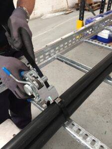 centers, UPS distribution, or MV industrial feeders, the installation often needs a cleat that delivers high strength without creating installation challenges. That combination is exactly where BAND-FAST Cable Cleats excel.
BAND-FAST is designed for circuits with peak fault currents up to 120kA delivering the strength expected of high rating stainless steel or reinforced cleats while also allowing crews to secure cables after the pull. Post pull installation is a major advantage in dense trays, vertical risers, and constrained overhead spaces where traditional bolt style cleats can slow progress or require awkward cable manipulation.
Because BAND-FAST is tested to the electromechanical requirements defined in IEC 61914, it can safely restrain single core conductors in trefoil configurations commonly used for LV, MV, and HV distribution. The systems’ configuration provides reliable retention through high-fault events while protecting the cable jacket during movement.
Slot Width Requirements
To ensure proper engagement with the tray or ladder, BAND-FAST needs to be used with rung slots that meet BAND-IT’s dimensional guidelines:
| Compatible Rung Slot Widths |
|
| BAND-FAST | Slot Width |
| Coated 5/8″ BAND-FAST | ≥17.5mm |
| Uncoated 5/8″ BAND-FAST | ≥17mm |
| Uncoated 3/4″ BAND-FAST | ≥20mm |
If rung slots are narrower, the band may not align or feed consistently; in this case, a ridged cleat may be more appropriate.
Why BAND-FAST is Used in High-Fault Applications
BAND-FAST is used most often in the following scenarios:
- Fault currents within the 120kA range where strong retention is required in tight installation spaces.
- Trefoil dimeters fall within ~70mm, especially when there are varying diameters, enabling one cleat SKU to cover a wide diameter range without jumping between bolt cleat sizes.
- Access is limited. Overhead trays, mezzanines, UPS corridors, or multi-bundle runs where underside access for bolt cleats is restricted.
- Prestaging cleats would interfere with rollers or cable pulling, since BAND-FAST installs after cables are set in place.
- Reducing SKU complexity, because BAND-FAST eliminates the narrow size increments common with ridged cleats.
The BAND-FAST Cable Cleat’s ability to tension in confined spaces combined with broad diameter coverage makes it especially effective in electrical builds where speed and footprint reduction are priorities.
Traditional Cleats That Can be Replaced With BAND-FAST
- Aluminum Trefoil Cleats (Panduit CCALTR Aluminum Trefoil): Aluminum trefoil cleats provide good strength but require precise alignment and torque, often forcing installers to prep hardware before pulling the cable. BAND-FAST offers the same retention level up to ≤120kA and can be installed after the pull, eliminating staging and keeping the cable path clear.
- Stainless Steel Mechanical Trefoil Cleats (Ellis Vulcan + SS): Stainless trefoil cleats are strong but bulky, need extra space for hardware, and require torque tools. These are attributes that data-center gray spaces rarely allow. BAND-FAST delivers similar retention up to 120kA and lets crews secure conductors quickly from above the tray.
- Heavy-Duty Composite or Polymer Trefoil Cleats (CMP Valiant 1BCAL): High-strength polymer cleats offer corrosion resistance and moderate-to-high retention ratings but require diameter specific SKUs. BAND-FAST covers a wide diameter range with a single part number, simplifying procurement and onsite inventory management.
- High Rating Stainless & Composite Cleats for Offshore & Industrial (CMP Patriot SDSS): These cleats deliver excellent mechanical performance but introduce installation complexity due to the size and number of their components. BAND-FAST provides an alternative when crews need a faster, more flexible installation method without compromising performance.
Why BAND-FAST is the Practical Choice
Today’s LV/MV/HV feeders, especially in data center and UPS environments, run through tightly packed trays where labor efficiency and cable protection are critical.
In these spaces, BAND-FAST has several practical advantages:
- Installs after the pull, avoiding the need to pre-stage cleats.
- Requires no torque or hardware alignment.
- Works effectivity in vertical, overhead, or congested runs.
- Provides wide diameter coverage, reducing SKU requirements.
- Short Circuit tested per IEC 61914.
- Integrates with BAND-IT tools such as the DT2000 for consistent, repeatable tension.
When tray slot width meets BAND-IT’s required dimensions, BAND-FAST offers strong balance between performance speed and adaptability, making it the dependable choice for high-fault restraint across a wide range of cable installations.
Reach out to BAND-IT for design support and cleat recommendation tailored to your project.
Learn more about how we supported two data center builds with the BAND-FAST cable cleat.