

How Cable Cleats Help High-Density Data Centers Route More Power
May 18.2026
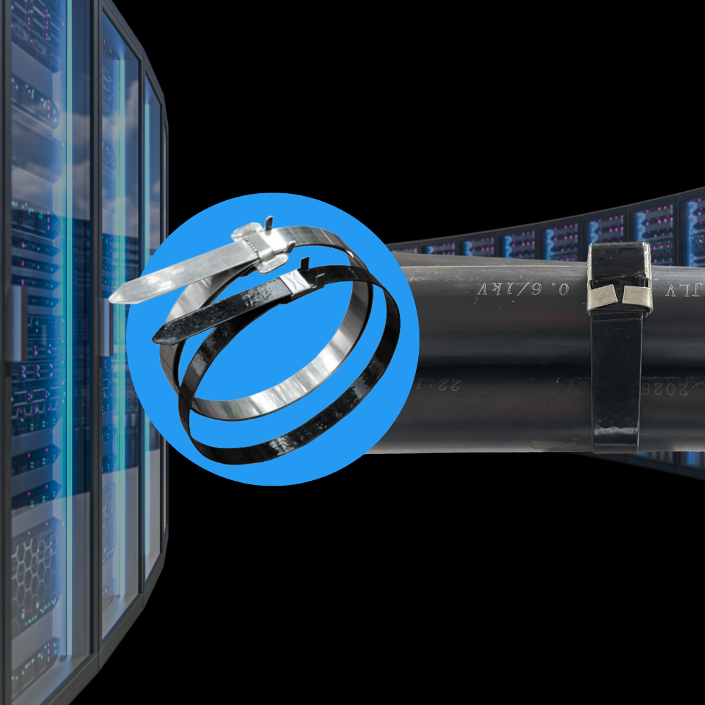
Data centers are being redesigned around one hard reality: rack power density keeps climbing, and the electrical backbone has to keep up; safely, efficiently, and with room to grow.
Industry forecasts and field reporting show data center electricity demand rising rapidly, driven largely by AI-optimized compute and the infrastructure built to support it. For example, the U.S. Department of Energy highlights that U.S. data centers consumed 176 TWh in 2023 (about 4.4% of total U.S. electricity) and could reach 325–580 TWh by 2028 – up to 12% of total U.S. electricity. Gartner projects worldwide data center electricity use doubling by 2030, with AI-optimized servers becoming a major share of that load. Berkeley Lab similarly forecasts aggressive growth in grid power needs through the decade.
All of that power still has to move from utility or on-site generation to switchgear, transformers, UPS systems, BESS, PDUs, and ultimately racks. As the “power chain” scales, engineers and contractors are evaluating a wider set of voltage levels, distribution configurations, and wiring methods than ever before. The 2026 NEC updates and industry commentary reflect that shift, especially as medium-voltage practices and grounding/bonding guidance continue evolving to match modern data center realities.
This article looks at what’s changing in data center power delivery as densities rise and why “routing” is becoming a first order design constraint again, not just a construction detail. Across the industry, teams are weighing multiple ways to move more power through the facility while preserving scalability and maintainability. As one example, the Open Compute Project’s Data Center Facilities work describes these shifts as a staged transition shaped by real site requirements and ecosystem maturity, rather than a single prescribed architecture.
Why “More Power” Starts at the Rack
For years, ‘high density’ was mostly confined to a few purpose-built pods or zones. Today, it’s increasingly being treated as a baseline planning assumption, especially for AI clusters and accelerated compute. That demand is pushing electrical and mechanical design decisions earlier in project cycles and forcing design teams to ask different questions:
- How quickly can we scale rack power without having to redesign major feeders, tray routes, or power blocks as density assumptions evolve?
- Where does raising voltage reduce current, conductor mass, and losses in a way that stays scalable?
- How do we keep routing flexible when the IT load mix changes faster than building lifecycles?
The industry is actively exploring higher-voltage architectures at multiple levels, from facility distribution voltages to emerging rack-level concepts. For example, Google has described the shift from 48-V DC toward ±400-V DC as a way to support 100 kW to 1 MW IT racks, and industry coverage of 800-V DC roadmaps points to the same underlying driver; delivering more power while avoiding a proportional increase in current and copper.
The outcome: even when a facility has enough megawatts on paper, the real bottleneck becomes deliverability; how efficiently you can route that power where it needs to go. OCP’s staged view frames the transition as being driven first by ‘compute densification and congestion management’; a reminder that power architecture decisions increasingly show up as physical routing constraints in real buildings.
Higher Voltage in Data Centers: Why It’s Trending (and What It Changes)
In OCP’s DCF LVDC white paper the authors compare multiple power distribution approaches and note that higher distribution voltage reduces current for the same delivered power; one reason higher voltage options keep showing up in next generation data center discussions. As power density rises, many teams look at higher voltage because it can:
- Deliver the same power with lower current
- Reduce conductor size or the number of parallel set
- Improve voltage drop performance on long runs
- Reduce losses and congestion in certain parts of the distribution path
At the same time, higher voltage changes the physical routing conversation. It often leads to:
- More single-conductor cable runs (especially as feeders get large)
- More emphasis on ampacity in cable tray, spacing, and thermal behavior
- More scrutiny of grounding/bonding protection coordination, and medium voltage practices; topics increasingly emphasized as the NEC evolves to reflect modern data center realities.
Why Engineers Keep Considering Cable Tray / Ladder Tray for High-Power Routing
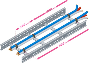
When power levels climb, designers typically evaluate several wiring methods (busway, conduit, cable tray/ladder tray, etc.). Ladder type cable tray (ladder tray) remains common in high-power segments because they’re:
- Scalable (add circuits without rebuilding an entire raceway system)
- Accessible (easier maintenance, inspection, and expansion)
- Efficient to install (especially for large feeders where conduit pulls become labor-heavy)
- Thermally favorable when ventilation and spacing are managed appropriately
But open routing has tradeoffs, and those tradeoffs are exactly where engineers start talking about conductor arrangement and restraint. Similar routing logic is showing up in adjacent high-power builds, too. Electrical Contractor Magazine notes that many BESS projects are shifting cables aboveground because trenching is cumbersome and costly in tight layouts, and because aboveground runs can reduce heat buildup compared to buried cable paths. The same piece also highlights that these aboveground runs often rely on cleats to restrain cables during electrical faults, helping prevent cables from separating under fault forces and damaging terminations.
That’s the same “open pathway” reality you run into in data centers when large single conductors are routed on ladder tray; once you’ve chosen open tray for scalability and access, the next question becomes how conductor arrangement and restraint keep the route predictable as density rises.
Open Tray + Single Conductors: Why Arrangement Matters (Trefoil/Triad vs Flat-Spaced)
When power routing shifts toward single conductors on open tray, the question isn’t just how to get from A to B, it’s how to keep the circuit behaving predictably as density rises. In practice, that often comes down to phase arrangement (how the conductors sit relative to one another) and how consistently that geometry is maintained over long runs and through changes on the jobsite.
That’s why you’ll see engineers and electricians talk about arrangements like trefoil/triad and flat-spaced. For example, trefoil keeps the phases tightly grouped in a repeatable formation; flat-spaced can be attractive when teams are balancing tray width, terminations, and thermal considerations. Either way, open tray puts more emphasis on preventing excessive movement during fault conditions, language echoed in NEC commentary around keeping single conductors securely bound in circuit groups (392.20(C)).
Why Use Single-Conductor Cables Instead of Triplexed (or 3-Conductor / Multicore)?
As feeder power climbs, the decision often shifts from “what’s ideal on paper” to “what’s buildable, serviceable, and scalable in the real world.” In many high-power segments of the data center power chain, single conductors routed on tray remain in the mix because they give teams more flexibility in how they stage pulls, manage physical routing constraints, and plan for future growth.
That doesn’t make triplexed or multiconductor cable “wrong.” They can be a great fit where cable sizes, run lengths, and installation conditions stay within practical limits. But as current levels and pathway congestion increase, teams would consider single conductors because they can reduce handling challenges and preserve options when layouts evolve. In those cases, the discussion moves to how conductors are arranged and restrained so the routing strategy remains reliable under both normal operation and fault conditions.
Common reasons teams lean toward singles at higher power:
- Constructability: generally easier handling and routing as cable size, weight, and bend radius increase
- Scalability: parallel sets and future additions can be simpler to plan and execute
- Serviceability: damaged conductors can be addressed with less disruption in some scenarios
- Pathway efficiency: often more control over how circuits fit and remain organized in dense tray runs
The Tradeoff of Open Cable Tray: Exposure (and Where Restraint Fits)
Open tray and ladder tray help teams move a lot of power through a facility efficiently, but the tradeoff is that the installation becomes more sensitive to geometry (how conductors are arranged and how well that arrangement is maintained over time). As cable density rises, small variations in spacing, grouping, and support can turn into real constraints: thermal behavior can become harder to predict, pathways get harder to keep organized, and “as built” routing can drift from “as designed” faster than most teams want.
Fault conditions are the other side of the equation. In U.S. code discussions around cable tray installations, the theme is consistent; when single conductors are used (particularly in parallel sets) proper grouping, spacing, and support are required, with industry practice recognizing the need to limit movement under fault-current magnetic forces. In parallel, OCP’s DCF LVDC work underscores a broader industry reality in high power systems; system level fault behavior (including peak fault current and I²t) drives mechanical requirements such as “magnetic force capability” and “mechanical locking” of the power path, because that’s what protects equipment and keeps the system recoverable when something goes wrong.
This is where cable cleats fit without forcing a single architecture. In dense tray runs, cleats are one of the purpose-built tools teams use to:
- Maintain conductor geometry (trefoil/triad or flat more consistently along the run, not just at a few tie points
- Support higher density routing by keeping circuit groups controlled and organized as tray fill increases (less “sprawl,” fewer surprises at pull/termination).
- Reduce risk during fault events by restraining the movement that can damage adjacent circuits, tray hardware, or terminations (look for them to be tested to IEC 61914)
- Make open-tray routing more defensible by aligning the installation with the “securely bound / prevent excessive movement” intent that shows up in U.S. guidance (NEC 392.20(C)) and field discussion
In other words, as tray routes get denser, cleats help teams keep conductor geometry controlled and consistent, reducing install variability and fault-event movement risk, which is often what makes “more power” achievable in practice.
Cable cleats don’t replace architecture decisions like voltage level, busway vs tray, or distribution topology, but they can strengthen the tray based portion of a high power routing strategy by helping teams maximize pathway utilization while keeping conductor grouping and restraint consistent as systems scale. Once restraint is on the table, the next question becomes where in the data center power path it tends to matter most.
Where Cable Cleats Fit in the Data Center Power Path (Quick Orientation)
If you want a more detailed walkthrough of typical “where they show up,” we’ve already mapped it in:
Where Are Cable Cleats Used in Data Centers?
Selecting the Right Cable Cleat: A Complete Guide
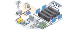
In short, cleats most often appear in and around gray space routes (between major electrical equipment), where fault energy and conductor size are highest.
Conclusion
Rack density is rising, and the impact doesn’t stop at the rack. It pushes upstream into voltage decisions, equipment topology, and the physical realities of routing power through a facility that still has to be buildable, serviceable, and expandable.
That’s why many teams continue to evaluate ladder tray / cable tray strategies using single conductors, paired with conductor arrangements like trefoil (triad) or flat-spaced layouts to manage heat and fault-current behavior. And, it’s why cable cleats remain an important complementary tool; they help reinforce the routing approach engineers choose by providing short-circuit restraint where open tray runs and high fault energy intersect.
If you’re planning higher density backbone routes or looking for practical ways to maximize tray utilization while keeping higher power routing scalable, BAND-IT can help you evaluate the right mechanical restraint and short circuit protection to complement your broader distribution strategy. Talk with our team about cable cleat solutions that support dense cable runs and help maintain conductor geometry where fault energy and open tray routing intersect; Contact Us
FAQ
What do cable cleats do?
Cable cleats provide mechanical restraint for power cables routed on open support systems like ladder tray. In high power runs (especially with single conductors) they help maintain circuit grouping (trefoil/triad or flat spaced layouts) and restrain cable movement during short circuit events, which supports safer, more predictable routing as tray density increases.
Do cable cleats increase ampacity?
Cable cleats aren’t an ampacity tool by themselves. Ampacity is driven by conductor size, insulation rating, ambient conditions, spacing, and installation method. What cleats can do is support the physical routing approach engineers select (trefoil or flat-spaced) and help maintain that geometry consistently, especially on long ladder tray runs where spacing and grouping matter.
Are cable cleats only for trefoil?
No. Cleats can be used in multiple configurations (single, trefoil/triad, and other grouped arrangements). Trefoil/triad is simply one of the most common places they provide clear value because the phases are grouped intentionally, and fault forces can be significant.
Why do engineers talk about trefoil in the first place?
Because trefoil can reduce net magnetic field around the circuit and help manage induced effects and heating concerns compared with some flat arrangements, especially when routing large single-core conductors.
How does NEC relate to cleats?
NEC language (392.20(C)) and common industry commentary emphasize grouping and securing parallel conductors in tray to avoid current imbalance and to prevent excessive movement due to fault-current magnetic forces. Many engineers treat engineered restraint (like cleats) as a practical way to satisfy that intent in high-fault, high-power tray routes.