
Where Are Cable Cleats Used in Data Centers?
April 27.2026
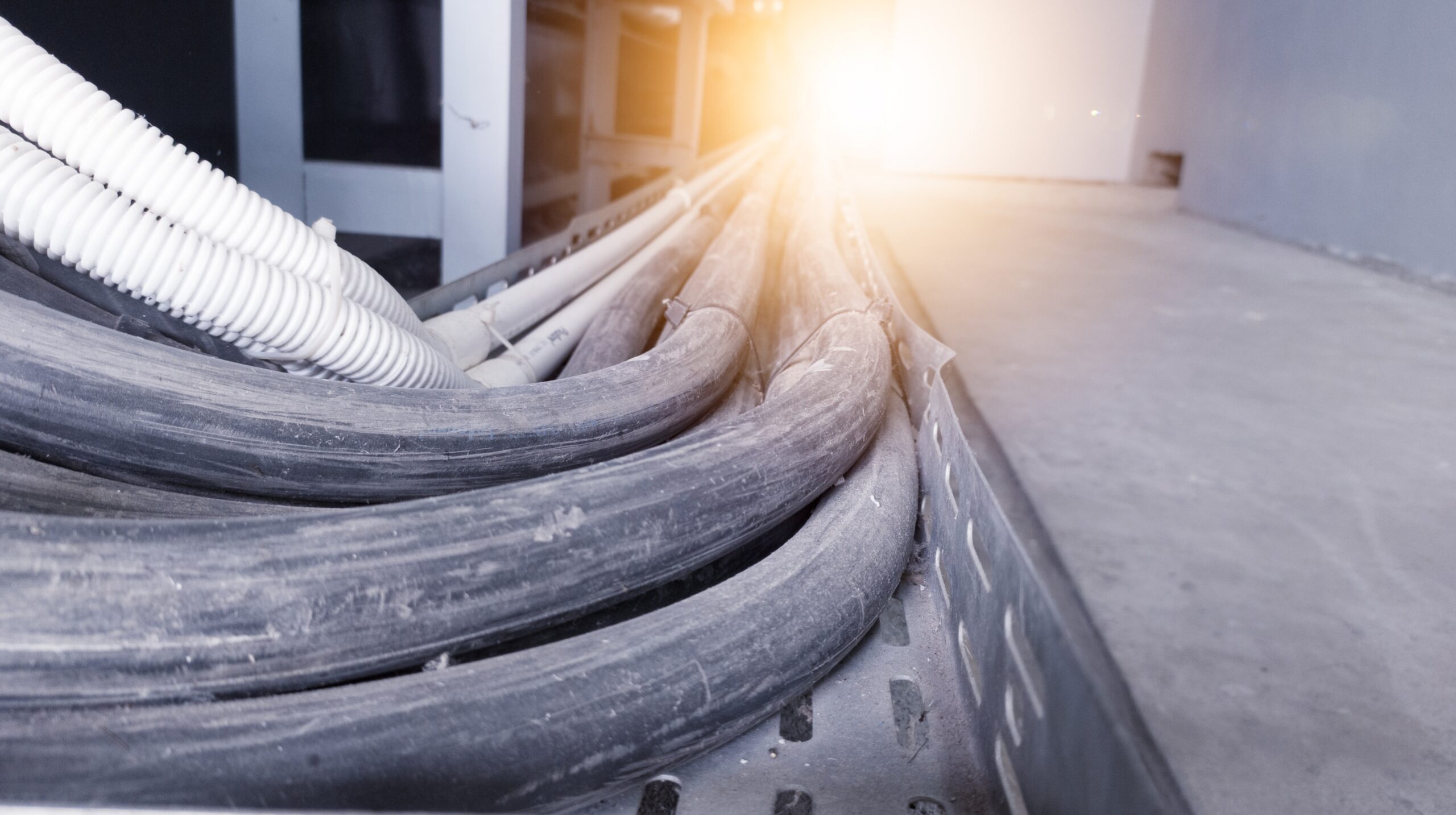
Data center power distribution continues to evolve as rack densities increase and facilities demand greater scalability, flexibility, and resilience. In North America, many of these demands are met through cable‑based power distribution, with large low‑ and medium‑voltage conductors routed on ladder‑type cable tray systems across backbone routes in and around gray space. While electrical protection and equipment ratings are well understood, the mechanical behavior of power cables during short‑circuit events is often less clearly defined in practice.
Cable cleats address this specific condition by providing engineered restraint where exposed conductors may be subjected to short‑circuit mechanical forces. Understanding where cable cleats are actually used in data centers, and why they appear repeatedly in certain parts of the electrical system, requires looking at how power is routed, how cables are installed, and where fault energy and open pathways intersect.
This article walks through the data center power path, the wiring methods commonly selected, and the cable characteristics that drive restraint decisions, with a focus on North American practice and practical application rather than theory.
In summary:
In data centers, cable cleats are used on ladder‑type cable tray systems carrying large, parallel low‑ and medium‑voltage power cables along high‑energy backbone and equipment‑to‑equipment distribution routes, particularly in and around gray space.
1. Definitions
1.1 LV, MV, HV (US-centric voltage classes)
In North American facilities, you’ll often hear ‘low-voltage’ used informally to mean the 600 V class distribution commonly found inside buildings. In this article we use ANSI C84.1 voltage classes for precision, and we call out ‘600 V class’ explicitly when relevant.
- Low-Voltage (LV): 1,000 V or less
- Medium-Voltage (MV): > 1,000 V and < 100 kV
- High-Voltage (HV): ≥ 100 kV and ≤ 230 kV
For practical facility design discussions, MV is often described as the distribution band used for large campuses and high-demand sites, while HV is more typical of transmission.
How we use these terms in a data center context: Most on-site distribution decisions revolve around LV and MV, with HV typically upstream on the utility side.
1.2 White space vs gray space (data center layout)
Commonly used industry definition:
- White space is the IT equipment area (racks/cabinets) and the immediate environment supporting IT operation.
- Gray space houses backend infrastructure such as switchgear, transformers, generators, UPS systems, and cooling plant.
This distinction matters because many of the highest‑energy cable runs, and areas where available fault current is highest, are typically found in or near gray space.
What the National Electrical Code (NEC) requires, and why cable restraint details can vary
What the NEC requires: In U.S. practice, we start by matching equipment and protective devices to the available fault current at the point of installation, including suitable interrupting ratings for overcurrent protective devices and adequate short-circuit current ratings (SCCR) for equipment assemblies.
Why restraint choices are sometimes unclear in the field: The Code is very clear on electrical ratings, but it is often less specific about the exact mechanical method to control cable movement in open support systems such as cable tray during a short-circuit event. That is why the industry commonly relies on tested restraint solutions, and why cable cleats are evaluated against IEC 61914, which is widely positioned as the most globally recognized cable cleat testing standard and a practical way to demonstrate short-circuit restraint performance.
2. Where power is routed in a data center, a practical to and from map
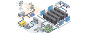
A clear way to understand where cable restraint becomes relevant is to follow the electrical path from the utility supply to the information technology (IT) load, noting where high-energy cabling is typically concentrated and where cable pathways are commonly open and accessible for maintenance and expansion. In practical terms, cable cleats are applied in these open, cable‑based power distribution segments, particularly where large conductors are routed on ladder rack or cable tray between major pieces of electrical equipment.
Two fundamentals help keep this discussion accurate in a North American context. First, fault exposure is location-specific; available fault current is the maximum fault current available at a point and it varies based on system parameters and where the point is located in the system. Second, the areas commonly called ‘gray space’ (the backend electrical and mechanical plant) frequently contain the highest concentration of major electrical equipment and the densest power pathways, which is why they are frequently referenced in discussions of fault consequence management.
2.1 Utility supply to service entrance or site substation
Many large data center sites receive one or more medium-voltage (MV) feeds from the utility, then route that power into service entrance equipment or a site substation function that establishes the primary switching, protection, and redundancy scheme for the facility. In practical terms, this is where the facility begins translating incoming power into a distribution architecture that can support continuous operation and planned growth, including multiple feeders, transfer strategies, and segmentation of critical and non-critical loads.
In many designs, MV is used for site distribution across a campus, then power is stepped down closer to the load, because distributing at higher voltage reduces current for a given power level and can simplify infrastructure. This is also the first point in the chain where designers begin thinking about how downstream cable pathways will be routed and maintained, because decisions made here drive feeder sizes, equipment footprints, and the number of downstream distribution points.
2.2 MV switchgear to transformers to low voltage distribution
A common architecture is medium-voltage switchgear, then transformer, then low-voltage (LV) switchgear or switchboard, before power is routed to uninterruptible power supplies. This is typically located in what the industry often calls ‘gray space’, the backend infrastructure zone that houses transformers, switchgear, generators, uninterruptible power supplies, and other supporting plant.
This segment is where high-capacity feeder runs and equipment terminations are often concentrated, and where routing methods such as ladder-type cable tray, sometimes called cable ladder, are frequently selected to manage high cable density with accessible pathways and favorable thermal characteristics. These transformer secondary and low‑voltage distribution runs are a primary application area for cable cleats, because they combine high available fault current with cable‑based routing in open support systems.
2.3 LV distribution to uninterruptible power supply and maintenance bypass
From the LV distribution lineup, power is routed into an uninterruptible power supply (UPS) system, typically with a maintenance bypass path, so the facility can maintain continuity through upstream disturbances and switching events. This part of the chain is commonly cable-dense because it includes both normal and bypass feeds, monitoring, protection, and multiple distribution branches.
From a short-circuit and protection standpoint, this is also a region where the available fault current should be understood and documented, since equipment selection and protective device ratings must be appropriate for the fault current available at the point of installation. In data center discussions, this is one reason suppliers highlight gray space electrical infrastructure as a zone where fault consequences need to be managed carefully. Where UPS input, output, and bypass conductors are routed in cable tray or ladder rack, cable cleats are commonly used to control conductor movement during short‑circuit events.
2.4 UPS output to downstream distribution, power distribution units and remote power panels
After the uninterruptible power supply (UPS), conditioned power is routed through cable‑fed distribution equipment that bridges gray space into the information technology (IT) load areas, most commonly power distribution units (PDUs) and remote power panels (RPPs). These sections of the power path are typically supported on ladder rack or cable tray systems to accommodate high cable density, accessibility, and ongoing change. In these cable‑fed distribution paths, especially where multiple large conductors are grouped on ladder rack or cable tray, cable cleats are used to provide tested restraint under short‑circuit forces.
In North American baseline designs, a widely applied framework is distributing power at 480 volts and stepping down closer to the IT load. Historically, that step‑down often produced both 208 volts and 120 volts, but as rack power densities have increased, most modern IT equipment is now supplied at higher utilization voltages, most commonly 208 volts line‑to‑line or 230–240 volts. This shift reduces current, conductor count, and pathway congestion compared to 120‑volt delivery, which has become increasingly impractical at higher rack loads.
Alternative utilization strategies, such as 415/240‑volt architectures, are used to make 240 volts available line‑to‑neutral for many IT loads, reducing or eliminating intermediate transformation stages depending on site design and equipment compatibility. Across these approaches, the common driver is the same: rising rack power densities have pushed facilities toward higher utilization voltages to manage current levels, cable volume, thermal performance, and physical routing constraints in the distribution system.
2.5 Final delivery to the rack and cabinet power distribution
At the final stage, power is delivered to racks and cabinets through rack‑level distribution, typically using rack power distribution units (rack PDUs) aligned with the facility’s selected utilization voltage strategy. In the traditional North American distribution chain, power is commonly distributed at 480 volts, then stepped down closer to the IT load. While legacy designs often included 120‑volt delivery, modern data center loads are most commonly supplied at higher utilization voltages, such as 208 volts line‑to‑line or 230–240 volts, to better support increased rack power density and reduce current, conductor count, and pathway congestion.
In higher‑voltage rack distribution concepts, the design objective is to reduce the number of power conversions and associated losses by shifting where step‑down occurs or by aligning distribution voltage more closely with IT equipment utilization requirements. This evolution reflects the practical realities of modern server power supplies, which are designed to operate efficiently across wide input voltage ranges and favor higher utilization voltages as rack loads scale.
Regardless of the specific utilization voltage selected, data centers rely on cable‑based pathways that must accommodate high power density, frequent change, and long service life. For that reason, cable cleats are most commonly applied on backbone cable tray and ladder rack systems in and around gray space, where large feeder cables, equipment terminations, and the highest‑energy cable routes converge.
3. Pathway options, why cable ladder is the primary environment for cable cleats
We’ve established that cable cleats are applied along cable‑based, high‑energy distribution paths, particularly where large conductors are routed in open support systems between major pieces of electrical equipment. In data centers, that description most commonly aligns with ladder‑type cable tray, often referred to as cable ladder.
While several wiring methods are permitted and used in data center power distribution, ladder-type cable tray consistently emerges as the primary environment where cable cleats are specified, not because it is the only option available, but because of the role it plays in supporting dense, scalable, cable‑based power routing.
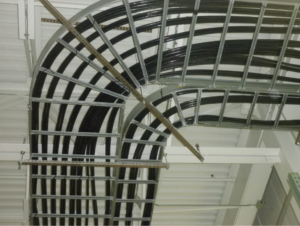
3.1 Ladder‑type cable tray (cable ladder), the primary cleat application environment
Ladder‑type cable tray is widely used in data centers for backbone power distribution because it is well suited to carrying large conductors, high cable volumes, and long parallel runs in accessible pathways. Its open construction supports airflow and heat dissipation, while its rungs provide predictable attachment points for maintaining cable position along the route.
From a cable restraint standpoint, these same characteristics are what make ladder tray the most common environment for cable cleats:
- Cables are exposed rather than enclosed, so physical movement during a short‑circuit event must be managed intentionally.
- Conductors are often large, single‑core cables installed in parallel sets, which experience the highest electromechanical forces under fault conditions.
- Pathways are typically accessible for inspection and modification, making engineered restraint both practical and maintainable over the life of the facility.
In short, ladder‑type tray creates both the need for restraint under short‑circuit forces and the physical framework where tested cable cleats can be applied at known intervals to control conductor movement.
3.2 Why ladder tray is favored over other wiring methods in data centers
It is common to ask why ladder‑type tray is used so extensively when other wiring methods are available. The answer is driven by operational realities rather than preference.
- Scalability and change: Data centers are built for continual expansion and reconfiguration. Ladder tray allows circuits to be added, re‑routed, or removed without the disruption and cost associated with pulling additional conduits or opening enclosed systems.
- Cable density and space efficiency: As power levels increase, routing power through individual conduits becomes impractical due to space and coordination constraints. Ladder tray consolidates multiple circuits into a manageable, organized pathway.
- Thermal performance: Open tray construction supports convective cooling and reduces heat buildup around loaded conductors, which is particularly important in high‑ampacity distribution runs.
- Visibility and inspection: Exposed routing enables easier inspection of cable condition, routing integrity, and support hardware over time.
These benefits explain why ladder‑type tray is frequently selected for transformer secondaries, low‑voltage distribution feeders, uninterruptible power supply pathways, and other backbone routes, and why cable cleats are so closely associated with these systems in practice.
3.3 How the other wiring methods differ in relation to cable cleats
Other wiring methods are still used in data centers, but they serve different purposes and often introduce tradeoffs in scalability, flexibility, or physical routing that distinguish them from ladder‑type cable tray. In most cases, they shift the restraint question rather than eliminate it.
Conduit: Conduit encloses conductors within a raceway, inherently limiting cable movement along the run and reducing the need for external restraint devices such as cable cleats. In data centers, conduit is frequently selected where physical protection or environmental sealing is the dominant requirement, including underground utility feeds, outdoor runs to generators, or protected transitions through walls and slabs. For internal power distribution, however, conduit becomes increasingly space‑intensive and difficult to scale as cable size and quantity grow, which is why it is typically limited to drops or short transitions rather than dense backbone routing served by ladder tray systems.
Cablebus: Cablebus is a cable‑based but fully enclosed system with internal supports designed to withstand short‑circuit forces, addressing conductor restraint through the product’s architecture. While this approach simplifies restraint along the run, it also represents a more rigid and pre‑engineered solution, with less flexibility to reconfigure or expand individual circuits compared to open cable tray systems that support incremental growth and modification.
Busway: Busway uses factory‑mounted conductors within a metal enclosure, shifting the design challenge from managing free‑cable movement to selecting and installing an enclosed distribution system with appropriate ratings and tap‑off strategies. Although busway can be effective for certain modular layouts, it reduces the role of field‑installed cable routing and therefore makes traditional cable cleats largely irrelevant within the busway run itself, while also offering less adaptability for mixed cable types or irregular routing compared to ladder‑type tray.
In contrast, ladder‑type cable tray remains the dominant wiring method wherever power is distributed using discrete cables in open, supported pathways. As a result, cable cleats are most commonly specified on ladder‑type cable tray systems supporting high‑energy, cable‑based distribution routes where conductors are exposed, scalable, and subject to short‑circuit mechanical forces.
4. The cable reality in data centers, what drives cable cleat use
This section examines the cable types, configurations, and power characteristics typically installed on ladder‑type cable tray systems in data centers, and why these conditions define where cable restraint is applied in practice.
In data centers, it is not simply the presence of cable tray that drives restraint decisions. It is the combination of large conductors, parallel cable arrangements, and high‑energy distribution routed through open, supported pathways that creates the need for intentional cable restraint.
4.1 Cable tray is not “anything goes”
Cable tray systems are governed by specific rules on what types of conductors are permitted, how they are installed, and how they are supported. In U.S. installations, only certain cable constructions and conductor types are allowed in tray, including tray‑rated multiconductor cables and, under defined conditions, larger single‑conductor (single-core) power cables.
This matters for cable cleats because tray‑permitted power conductors are often:
- Larger in diameter
- Installed in parallel sets
- Routed for long distances on ladder‑type tray
These characteristics directly influence how cables behave mechanically during short‑circuit events and why restraint must be addressed as part of the cable routing design.
4.2 Low‑voltage power cables in data centers
Low‑voltage (LV) power distribution forms the day‑to‑day backbone of most data centers, particularly between transformers, switchgear, uninterruptible power supplies (UPS), and downstream distribution equipment. As rack power densities increase, these LV feeders are typically larger and more numerous than in earlier designs.
For practical reasons, including space efficiency, accessibility, and change management, these conductors are commonly routed on ladder‑type cable tray, as permitted under National Electrical Code (NEC) Article 392, rather than in individual conduits. When low‑voltage feeders are installed in parallel on open tray systems, their size, spacing, and exposure make cable cleats a common specification to control conductor movement under short‑circuit mechanical forces, an aspect of cable tray installations governed structurally by NEC Article 392.20 but not prescriptively detailed for fault‑induced cable restraint, and therefore addressed through engineered restraint solutions.
4.3 Medium‑voltage power cables in data centers
Medium‑voltage (MV) distribution is increasingly used in larger and higher‑demand data centers to reduce current levels and conductor count over longer distances. In these facilities, MV cables may be routed on ladder‑type cable tray in gray space or electrical plant areas, depending on site design and utility interface.
Where MV cables are installed on open tray systems, they are typically larger in diameter and subject to greater electromechanical forces during fault conditions. In these applications, cable cleats are used to provide tested, repeatable restraint for cables that are both physically exposed and carrying higher fault energy.
The potential for MV cables to share tray infrastructure with LV feeders further reinforces the importance of consistent restraint strategies along these backbone routes.
4.4 Conductor Arrangement in Cable Tray Systems

In data center power distribution, large low‑ and medium‑voltage feeders are commonly installed as single‑conductor cables routed on ladder‑type cable tray. These conductors are often installed in parallel and routed over long distances along backbone and equipment‑to‑equipment pathways. How they are arranged on the tray (whether grouped closely, laid flat with spacing, or installed as factory cable assemblies) directly influences how they behave mechanically during fault conditions.
The National Electrical Code addresses these installations through separate requirements for ampacity, grouping, and mechanical restraint (Articles 310 and 392), rather than prescribing a single tray configuration. In practice, cable cleats are most often applied where conductor arrangement, exposure, and available fault current intersect.
Bundled single conductors
In some tray installations, single‑conductor cables are grouped or bundled together in single layers and supported in accordance with Article 392. This approach is commonly used where tray width is constrained or where conductors are intentionally kept close together as a circuit group along a backbone route.
Even when grouped, these large conductors remain subject to short‑circuit magnetic forces. Where bundled single conductors are routed through high‑energy areas such as near switchgear, transformers, or UPS systems, additional mechanical restraint is commonly applied to control conductor movement during fault conditions.
Flat‑lay single conductors with spacing
As an example of this installation style in data center applications, designers could specify flat‑laid single conductors with maintained spacing between phases, particularly on large feeders serving major electrical equipment. This arrangement would be selected to support heat dissipation and ampacity on open ladder‑type tray systems (Articles 310 and 392).
Although the conductors are spaced, they are still installed as a circuit group and exposed to significant electromechanical forces during short‑circuit events. Where these flat‑lay installations coincide with high available fault current and open tray routing, cable cleats are commonly used to maintain conductor position and limit movement under fault conditions, consistent with the intent of 392.20(C).
The NEC does not prescribe a specific restraint method or calculation approach; acceptance of the securing method is determined by the authority having jurisdiction.
Triplexed assemblies
Triplexed assemblies represent a different condition. In typical data center usage, triplexed cable refers to three phase conductors manufactured and installed together in the same overall sheath. Because conductor geometry and restraint are inherent to the cable construction, these assemblies are treated differently under the NEC and are explicitly exempted from the requirement to be securely bound in circuit groups (392.20(C)).
Why this leads to cable cleat use in data centers
Across data center power systems, cable cleats would most often be specified where large single‑conductor cables, parallel installations, open ladder‑type tray, and high available fault current occur together. These conditions are most commonly found along backbone tray routes and in proximity to major electrical equipment, which is why cable cleats consistently appear in these areas as part of the overall power distribution design.
Data center power systems commonly use single‑conductor cables installed in parallel sets, arranged either flat or in grouped, single layer configurations such as trefoil or quadrafoil, depending on design practice and routing constraints.
During a short‑circuit event, the electromechanical forces generated between parallel conductors are influenced by conductor spacing, geometry, and support interval. IEC 61914 addresses this behavior by defining test methods and configuration scenarios used to evaluate cable cleat performance, recognizing that cleats function by maintaining conductor position and spacing under fault conditions.
4.5 Cable conditions that guide restraint specifications in data centers
Across both low and medium‑voltage applications, the defining conditions for cable cleat use in data centers are consistent:
- Large power cables
- Parallel conductor installations
- Routing on open ladder‑type cable tray systems
- Location along high‑energy backbone and equipment‑to‑equipment routes
Where these conditions exist, cable cleats are used to manage the mechanical behavior of power cables during short‑circuit events, complementing the electrical protection addressed elsewhere in the system design.
5. Short-circuit forces and why restraint matters in cable-based systems
This section focuses on why open, cable‑based power distribution routes, particularly those installed on ladder‑type cable tray and carrying large, low, and medium‑voltage conductors, benefit from intentional cable restraint beyond basic support or cable management.
5.1 Short‑circuit events create mechanical forces
In North American designs, electrical protection focuses on ensuring overcurrent devices and equipment are rated for the available fault current. During a short‑circuit event, however, high current flows through conductors for a brief interval before protective devices clear the fault. During this time, electromechanical forces develop between parallel conductors, driven by their spacing, geometry, and level of support.
In enclosed systems, these forces are largely managed by the equipment housing. In open ladder‑type tray systems, they act directly on the cables themselves, making physical control of conductor movement a separate design consideration.
5.2 Why ladder‑type tray demands intentional restraint
Ladder‑type cable tray is favored for backbone routing because it supports scalability, accessibility, and high cable density over the life of the facility. Those same advantages mean conductors are supported but not contained, particularly along high‑energy equipment‑to‑equipment routes in gray space.
When large power cables are installed in parallel on open tray systems, uncontrolled movement during a short‑circuit event can lead to insulation damage, cable contact, or stress at terminations. For this reason, restraint strategies are most commonly applied along these ladder‑tray‑based backbone routes.
5.3 General cable securing versus short‑circuit restraint
In U.S. data center installations, it is common to see power cables in tray secured using general‑purpose methods such as nylon or heavy‑duty plastic ties. These approaches are familiar to installers and sufficient for basic cable organization and support during normal operation.
However, securing cables for routing purposes is not the same as restraining them during a short‑circuit event (see our guide on selecting the right cable cleat). General‑purpose ties are not designed, rated, or tested to manage the transient electromechanical forces produced by high fault currents in large power conductors. Under these conditions, ties can deform or fail, allowing uncontrolled cable movement that can increase damage severity during a fault.
In open ladder‑type cable tray systems carrying large, parallel conductors, U.S. design practice recognizes that fault‑event restraint is a separate consideration from routine cable management. Cable cleats are used in these environments because they provide engineered restraint intended to control cable movement during short‑circuit conditions, complementing the electrical protection required by applicable codes and standards.
5.4 How restraint fits into data center power design
In practice, restraint is applied where specific conditions converge: large power conductors, parallel installations, routing on open ladder‑type tray, and proximity to high‑energy distribution equipment. In these environments, cable cleats are selected as part of a coordinated approach that complements electrical protection, pathway selection, and equipment ratings.
For additional perspective on how engineered cable restraint is becoming a standard design consideration across power‑dense facilities worldwide, see Why Mechanical Cable Restraint Is Becoming a Global Baseline.
6. Where cable cleats are used in North American data centers
In North American data centers, cable cleats are used in specific, repeatable environments, not everywhere power cables exist. Their application is driven by how power is routed, how cables are installed, and where short‑circuit mechanical forces can act on exposed conductors.
Cable cleats are most commonly used where all of the following conditions intersect.
6.1 Cable‑based backbone power distribution
Cable cleats are applied wherever power is distributed using discrete cables, rather than enclosed conductor systems such as busway or cablebus. This most often includes feeder and distribution circuits connecting transformers, switchgear, uninterruptible power supplies (UPS), and downstream distribution equipment.
In these cable‑based systems, the conductors themselves are responsible for withstanding both electrical and mechanical effects during abnormal events, making intentional restraint part of the distribution design.
6.2 Ladder‑type cable tray systems (primary application)
The most common environment for cable cleat use in data centers is ladder‑type cable tray, sometimes referred to as cable ladder. Ladder tray is widely used for internal backbone routing because it supports high cable density, accessibility, and flexibility over the life of the facility.
Because ladder tray supports but does not enclose conductors, cables are exposed to fault‑induced electromechanical forces. Cable cleats are therefore used on ladder‑type tray systems to control conductor movement where restraint is required by design rather than assumed through enclosure.
6.3 Large power cables installed in parallel
Cable cleats are most often specified where large low‑ or medium‑voltage power cables are installed in parallel sets. Parallel installations are common in modern data centers due to increasing power density and ampacity requirements.
In these arrangements, spacing, geometry, and support interval influence how cables behave during short‑circuit events. Cable cleats maintain conductor position and separation to manage that behavior in a predictable, tested way.
6.4 High‑energy distribution routes and equipment transitions
Within data centers, cable cleats are concentrated along high‑energy backbone routes, particularly:
- Transformer secondary feeders
- Low‑voltage and medium‑voltage switchgear connections
- UPS input, output, and bypass pathways
- Equipment‑to‑equipment runs in gray space
These locations combine high available fault current with exposed cable routing and critical terminations, which is why restraint strategies are most consistently applied there.
6.5 Open pathways where cables are supported, not enclosed
Cable cleats are used where conductors are routed in open support systems, such as ladder‑type tray, and not fully contained within raceways or factory‑assembled enclosures. In North American practice, this distinction matters.
General cable support and organization methods may be sufficient for normal operation, but fault‑event restraint is a separate consideration in open pathways. Cable cleats address that condition by providing engineered restraint intended to perform during short‑circuit events.
Conclusion: Applying restraint with confidence
Modern data centers demand power systems that scale in density, flexibility, and reliability. As data center power density continues to increase, BAND‑IT supports the surge in high‑energy, cable‑based distribution systems used throughout modern facilities with our BAND‑FAST® cable cleat portfolio. As this article has shown, cable cleats are not a general housekeeping accessory, nor are they required everywhere power cables exist. They are applied intentionally and repeatedly in specific environments, cable‑based distribution routes, installed on open ladder‑type cable tray, carrying large, parallel conductors in high‑energy sections of the electrical system.
Understanding where cable cleats are used, and why, allows designers, specifiers, and installers to treat restraint as a purposeful part of the power distribution strategy rather than an afterthought. When applied correctly, cleats complement electrical protection, pathway design, and equipment ratings by addressing the mechanical realities of short‑circuit events in cable‑based systems.
If you are designing, expanding, or upgrading a data center and want to apply cable restraint with confidence, BAND‑IT offers a broad portfolio of engineered cable cleat solutions supported by global testing standards and real‑world application knowledge. Contact the BAND‑IT team to discuss your restraint requirements, and to ensure your system is designed for the conditions it may experience, not just the ones it sees every day.