

How to Specify and Evaluate Cable Cleats Using the Short-Circuit Data You Already Have
May 08.2026
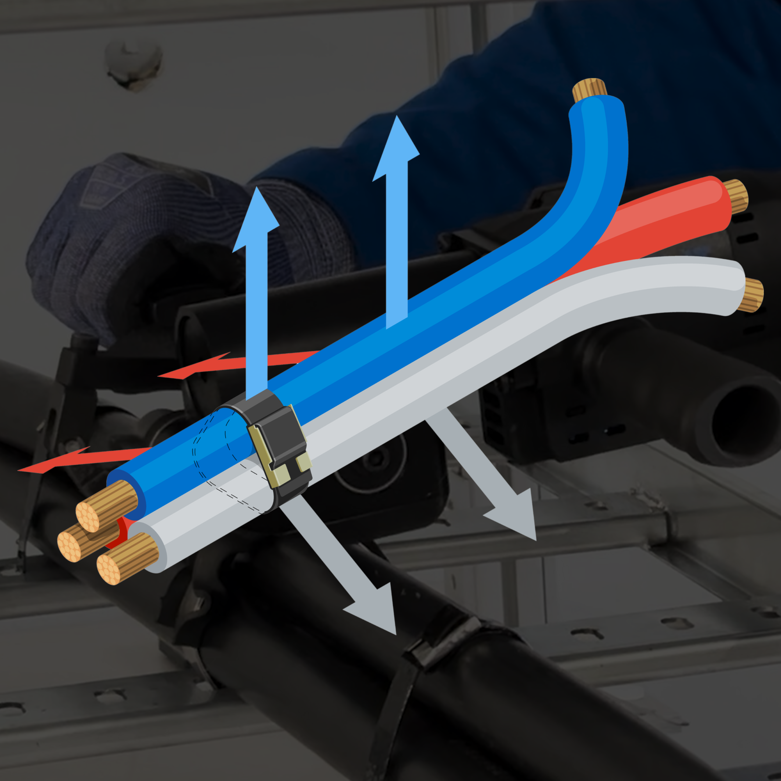
In zero‑downtime environments such as data centers and critical infrastructure, mechanical failure is not an option. With labor and materials frequently constrained, relying on post‑event repair is an unacceptable risk. Properly specified cable cleats help ensure that short‑circuit events do not escalate into prolonged outages driven by mechanical damage, rework, or delayed replacement.
By the time cable cleats are being specified, most electrical engineers already have the critical electrical information in hand. Short‑circuit studies performed in accordance with IEC 60909 or IEEE methodologies (such as IEEE 551 – the “Violet Book”) define fault levels, peak current, and system conditions with a high degree of confidence.
Where additional clarity is often needed is not on the electrical side, but at the point where those results must be translated into mechanical restraint performance. Cable cleats sit at that intersection. Their role is straightforward but critical; to ensure cables remain securely restrained when exposed to the extreme electromechanical forces that occur during a short‑circuit event.
This article focuses on how to use the short-circuit data you already have to specify and evaluate cable cleats correctly, without additional calculations and with clear alignment between electrical fault conditions and mechanical restraint performance. The goal is to help engineers make informed, defensible decisions that protect the physical integrity of the power cable system.
Start With the Correct Input: Peak Short‑Circuit Current
From a properly executed short‑circuit study (IEC 60909 or IEEE 551), engineers typically know:
- Peak short‑circuit current (iₚ)
- Initial symmetrical RMS current
- Fault locations along the cable route
- Cable arrangement (flat, trefoil*, or bundled)
*Trefoil (sometimes referred to as “triplexed” when the three phase conductors are supplied or bound together) refers to the triangular arrangement of three single-core phase cables and is the most aggressive standardized configuration evaluated under IEC 61914.
IEC 61914 is the international standard that defines how cable cleats are tested and classified for short-circuit electromechanical forces. This information is sufficient to evaluate cable cleats correctly. In earlier design phases where only RMS fault current is available, peak short‑circuit current is typically derived as part of the final short‑circuit study and should be used for cable cleat selection once confirmed. Cable cleats are not sized based on load current, ampacity, or thermal limits. They are sized to withstand the peak electrodynamic forces generated during a short‑circuit event, which are governed by the maximum instantaneous (peak) short‑circuit current, not the RMS current. In practice, peak fault current (together with spacing and configuration) defines the mechanical demand on the cleat system.
What Short‑Circuit Studies Do Not Tell You
Short‑circuit studies are intentionally electrical in scope. They quantify fault current, but they do not (by themselves) describe how that current translates into mechanical demand on the cable system. Specifically, short‑circuit studies typically do not indicate:
- The magnitude of mechanical force acting on the cables
- How restraint spacing influences that force
- Whether two cable cleats with the same stated kA rating provide equivalent mechanical performance
- What mechanical margin exists between a given installation and the limits of tested performance
These questions are addressed by IEC 61914, the international standard that defines how cable cleats are tested, rated, and classified for electromechanical forces generated during short‑circuit events. IEC 61914 establishes the test methods, declared parameters, and performance boundaries that allow engineers to relate electrical fault levels to mechanical restraint capability. Understanding this distinction allows engineers to move beyond fault current alone and evaluate whether a cable cleat system is appropriately specified for the mechanical realities of a short‑circuit event.
Why IEC 61914 Is the Bridge Between Electrical Data and Mechanical Performance
IEC 61914 defines how cable cleats are tested to resist electromechanical forces during a short-circuit. Importantly, it requires manufacturers to declare performance based on tested conditions, not analytical extrapolation.
Declared performance includes:
- Peak short‑circuit current
- Cable arrangement (e.g., trefoil or flat)
- Cable size range
- Maximum tested cleat spacing
A kA rating without spacing is incomplete. This is the most common source of confusion in cable cleat specifications.
For data center owners and operators with global portfolios, IEC 61914 has become a practical reference point for aligning mechanical restraint practices across regions. Even in U.S. installations, where IEC compliance is not mandated, many mission‑critical projects adopt IEC‑tested cable‑cleat criteria to ensure consistency, predictability, and demonstrated performance under short‑circuit conditions.
Spacing Is a Mechanical Design Variable, Not an Installation Detail
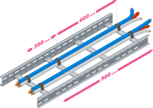
IEC 61914 Annex B shows that electromagnetic fault forces increase with the square of peak current and increase as restraint spacing increases. Engineers are not typically required to calculate these forces. The practical takeaway is straightforward: for a given fault current, increasing cleat spacing increases the mechanical load that each cleat must resist. That is why a cleat rated for a given kA level at 300 mm spacing may not be suitable at 600 mm spacing, even though the electrical fault level is unchanged.
How Tested Performance Drives Cleat Spacing
Cleat spacing is not selected arbitrarily. It is governed by what the cable cleat has been tested and declared to withstand under IEC 61914, taking into account peak fault current, cable configuration, and installation geometry. In practice, engineers do not evaluate unlimited spacing options. Instead, they select from declared spacing limits that balance mechanical performance with installation efficiency and overall project economics.
For example, 300 mm (12 in) and 600 mm (24 in) spacings are commonly specified, because they:
- Provide clear, review‑friendly spacing options that can be easily specified and justified
- Allow mechanical robustness to be increased by adjusting spacing, without redesigning cable routing or containment
From a design standpoint:
- 300 mm spacing provides higher restraint density and potential additional margin for higher fault levels or more onerous configurations
- 600 mm spacing balances mechanical performance with installation efficiency where fault levels and geometry allow
Other spacings may be declared for specific applications where tested performance supports them. Regardless of the spacing selected, spacing remains the primary lever engineers use to manage mechanical demand while optimizing the overall restraint solution.
Why kA Is the Governing Selection Parameter, Even Across Multiple Cable Diameters
Short‑circuit current is the dominant factor in cable‑cleat selection. The magnitude of electrodynamic fault forces is governed by peak short‑circuit current, conductor spacing, and cable configuration. Cable outside diameter influences force indirectly, through its effect on conductor center‑to‑center spacing, but it does not change the potential electrical fault duty itself.
In practice, cable OD defines:
- Whether a cable physically fits within a given cleat, and
- Whether the cleat’s tested and declared short‑circuit rating applies to that cable size
As long as:
- The cable OD falls within the manufacturer’s declared size range, and the maximum tested cleat spacing is not exceeded, the peak short‑circuit current (kA rating) governs cleat selection.
This is why a single cable cleat design may be qualified across a range of cable diameters at the same short‑circuit level, provided the cable OD range and spacing limits are declared by the manufacturer and supported by IEC 61914 short‑circuit testing.
Why Band‑Style Cable Cleats Work Across Multiple Configurations
Band‑style cable cleats are commonly used in flat, trefoil, and bundled arrangements because their load path is inherently configuration‑agnostic
From a mechanical standpoint:
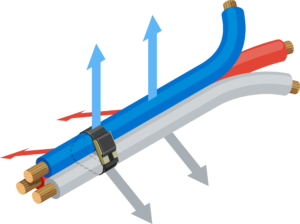
- Electromagnetic forces generated during a short‑circuit event act to rapidly separate phase conductors
- The most severe standardized interaction occurs when all three phase conductors act simultaneously
- The trefoil arrangement produces the highest electrodynamic forces for a given peak current and spacing, making it the most aggressive configuration addressed by IEC 61914

When tested under IEC 61914:
- Cable cleats are evaluated at a defined peak short‑circuit current
- At a defined maximum spacing
- Using a defined cable size and installation arrangement, with trefoil testing commonly used to establish the bounding mechanical case for restraint performance
If the manufacturer declares that performance applies across multiple configurations, that declaration is grounded in the fact that:
- Trefoil represents the most onerous standardized configuration
- Less severe configurations fall within the same mechanical envelope when spacing and current limits are respected
This is why a properly tested band‑style cleat can be applied confidently across multiple installation geometries, as declared by the manufacturer, when spacing and fault limits are respected.
How Engineers Should Evaluate Cable Cleat Ratings
When comparing cable cleats, the right questions are:
- What peak short‑circuit current was the cleat tested to?
- At what maximum spacing?
- For which cable size range?
- Under which configurations, as declared by the manufacturer?
- Was performance established through IEC 61914 testing?
General‑purpose cable ties or banding systems that are not specifically tested and rated to IEC 61914 should not be relied upon for mechanical restraint under short‑circuit fault conditions, regardless of their apparent strength in non‑fault applications.
Writing Clear, Defensible Specifications
A robust cable cleat specification should include:
- Peak short‑circuit current at the cable location
- Cable arrangement(s) (trefoil, flat, etc)
- Required cleat spacing (e.g., 300 mm or 600 mm)
- Compliance with IEC 61914 electromechanical force testing
- Cable OD
This approach ensures the correct restraint solution is specified and reduces the risk of misapplication during procurement, submittals, and installation.
Why This Matters in the Field
During a short-circuit, cable movement occurs in milliseconds. There is no opportunity for redistribution or correction. The restraint system either performs as intended, or it does not.
BAND‑IT cable cleat solutions are engineered and tested with this reality in mind:
- Performance is established through IEC 61914 testing
- Ratings are tied to declared spacing, current, and cable size
- Designs provide predictable mechanical restraint under fault conditions
For engineers, that means fewer assumptions, clearer specifications, and confidence that the installed system will behave as expected when it matters most.
Final Takeaway
In mission‑critical electrical systems, mechanical fault protection cannot be an afterthought. Ensuring that cable restraint systems are properly specified for short‑circuit forces is essential to maintaining availability and protecting the installation. For application‑specific support and engineered cable cleat solutions tested to IEC 61914, contact BAND‑IT to help ensure your designs are built for the realities of fault conditions.