

Why Fault Current Isn't Just an Electrical Problem: The Critical Role of Cable Restraint Systems
August 21.2026
Understanding available fault current, mechanical forces, and the role of IEC 61914 testing
If you’ve never witnessed a short-circuit test, it’s easy to think of fault currents in terms of calculations, studies, and equipment ratings. That changes once you watch a cable move under fault conditions. In a fraction of a second, an electrical fault can generate powerful electromechanical forces between conductors. Heavy low voltage (LV) or medium voltage (MV) cables that appear stationary under normal operation can experience sudden movement as thousands of amps flow through the system.
For electrical engineers, available fault current is a critical design parameter. It influences protective-device selection, equipment ratings, and system studies. But fault current also has a physical consequence that receives far less attention. The larger the fault current, the larger the forces the cable system may be required to withstand. That’s why understanding fault current is only part of the equation, the other part is understanding what happens mechanically when that fault occurs. Yet despite detailed fault studies, many projects spend far more time evaluating electrical protection than verifying how cable infrastructure will respond when those fault conditions occur.
(BAND-FAST® Short Circuit Testing, 2019)
What Is Available Fault Current?
According to NFPA 70E, available fault current is the maximum current that can be delivered to a point in an electrical system during a short-circuit condition. Importantly, available fault current is not the same everywhere throughout a facility. A service entrance, main switchboard, UPS output, battery energy storage connection, or branch distribution panel can all experience different fault-current levels. That’s because fault current is influenced by the electrical path between the energy source and the fault location. While electrical studies often focus on RMS fault-current values, the peak currents occurring during the initial fault cycles can produce the highest mechanical forces on cable systems.
What determines fault current? Many factors influence the amount of fault current available within a power system.
These include:
- Utility source strength
- Transformer kVA and impedance
- Generator and motor contribution
- Energy-storage systems
- Cable length
- Conductor size
- System configuration
- Protective equipment location
Of these variables, impedance is often one of the most important.
Impedance is the total opposition to current flow in an electrical circuit. In AC systems, impedance includes both resistance and reactance. As electricity passes through transformers, conductors, switchgear, and the cables themselves, impedance limits how much current can reach a downstream fault location. IEEE power-system guidance and industry fault-analysis methodologies consistently rely on impedance as a primary factor in fault-current calculations. Lower impedance generally means higher available fault current. Higher impedance generally means lower available fault current. This is why a fault located close to a transformer may experience significantly higher current than an identical fault farther away in the system.
Why the Power Source Matters
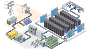
Available fault current is determined not only by the location of a fault, but also by the characteristics of the sources capable of supplying energy into that fault. As noted in IEEE Recommended Practice for Conducting Short-Circuit Studies and Analysis of Industrial and Commercial Power Systems, accurate fault-current calculations depend on system modeling and source contribution assumptions. Different sources respond differently during short-circuit conditions, which is why engineers evaluate source contribution as part of a comprehensive fault-current study.
Utility Service
Utility-connected power systems often produce the highest available fault-current levels because they are connected to large, interconnected generation and transmission networks. Available fault current is generally highest nearest the source and decreases as additional conductor and equipment impedance are added to the system.
Generators
Synchronous generators contribute fault current differently than utility sources. Following a fault, generator current is influenced by machine reactance characteristics, causing fault-current levels to change over time rather than remain constant. For this reason, generator-fed systems may exhibit fault-current characteristics that differ significantly from utility-fed systems, and generator contribution is routinely accounted for in short-circuit studies.
Rotating Equipment
Large motors can contribute fault current during the initial cycles of a short-circuit event. This motor contribution can increase the total fault current seen by protective devices and equipment and is commonly considered when determining short-circuit duties and equipment ratings.
Battery Energy Storage Systems (BESS)
Many battery energy storage systems (BESS) utilize inverter-based resources (IBRs), which behave differently during fault conditions than traditional synchronous machines. Unlike conventional generators, inverter fault-current response is largely governed by power-electronic controls and protection settings rather than machine physics alone.
Research from the National Renewable Energy Laboratory (NREL), a U.S. Department of Energy national laboratory, shows that inverter-based distributed energy resources (DERs) exhibit fault-current characteristics that differ significantly from conventional synchronous generators. Because inverter controls and power-electronic interfaces can regulate fault behavior, many inverter-based resources are designed to limit fault-current contribution during system disturbances. As energy storage, renewable generation, and microgrids become more prevalent, understanding source contribution is becoming an increasingly important part of fault-current analysis.
The Mechanical Forces Most Engineers Never See
Most conversations about fault current focus on:
- Switchgear ratings
- Circuit breakers
- Protective relays
- Arc-flash studies
- Short-circuit coordination studies
All are essential, but they only tell part of the story.
When high current flows through conductors, magnetic fields develop around the cables. These fields interact with one another, creating powerful electromechanical forces between adjacent conductors. IEC 61914 exists specifically because these forces can become large enough to move, damage, or displace inadequately restrained power cables during a fault. This standard has been referenced and carried over now into NEMA BI 50018-2024, C22.2 No.61914:23, and is being incorporated into a UL listing as well.
(Example of electromechanical forces damaging and displacing inadequately restrained power cables)
Faults play out over very short timeframes:
- Fault Occurs
↓
- Current Increases Rapidly
↓
- Electromagnetic Forces Develop
↓
- Conductors Attempt to Move
↓
- Restraint Systems React
↓
- Infrastructure Either Maintains Integrity or Experiences Damage
While electrical studies often focus on RMS fault-current values, the peak currents occurring during the initial fault cycles can produce the highest mechanical forces on cable systems. For many engineers, seeing these forces demonstrated during live testing is the first time the mechanical implications of a fault become tangible.
How IEC 61914 Testing Brings Theory Into Reality
A fault-current calculation tells engineers what may happen electrically. Testing helps demonstrate what may happen mechanically.
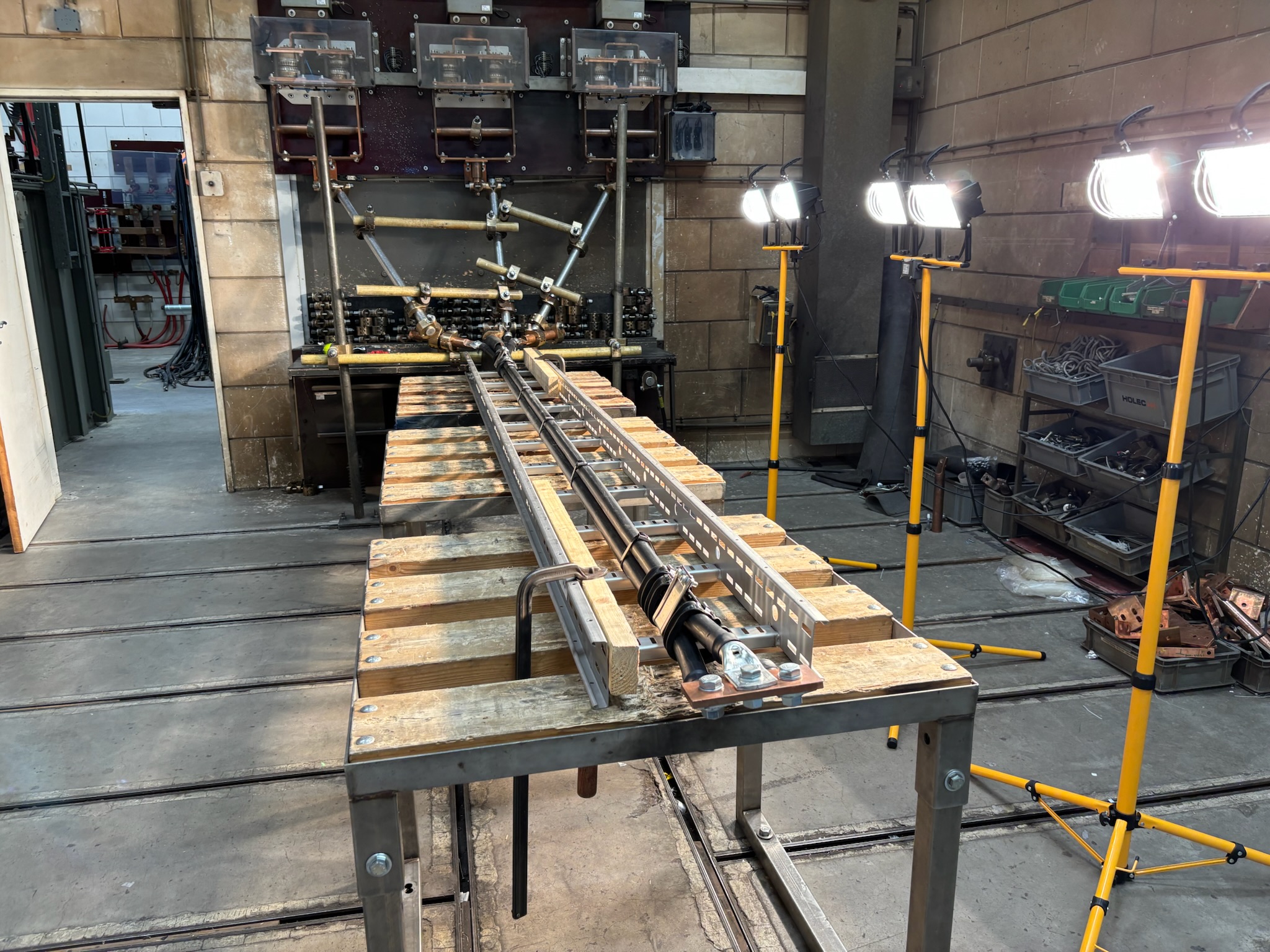
IEC 61914 establishes requirements for cable cleats used in electrical installations, including performance under short-circuit conditions where significant electromechanical forces can occur. During testing, cables are installed in representative configurations and subjected to controlled fault conditions designed to evaluate how the restraint system performs under severe mechanical loading. The objective is not simply to observe cable movement during a fault. It is to verify that the cable-cleat system, mounting structure, and associated hardware continue to perform their intended function when exposed to short-circuit forces.
(BAND-IT team setting up the testing rig for IEC compliance testing)
Testing evaluates the complete installation assembly, including:
- Cable configuration
- Cleat spacing
- Mounting structures
- Attachment hardware
- Intermediate restraints (where used)
- Overall cable retention and system integrity
After the short-circuit event, the assembly is inspected to verify that it continues to meet the standard’s performance requirements. Among other criteria, inspectors confirm that:
- Cable cleats remain securely attached to the mounting structure
- The restraint system continues to contain and support the cables as intended
- Cleats, restraints, and associated hardware remain intact
- No visible damage has been caused to the cable outer sheath by the restraint system
- The installation maintains its required post-test performance characteristics
This distinction is important; fault-current calculations help engineers estimate the magnitude of the forces that may develop during a short circuit. However, calculations alone cannot demonstrate how a complete cable restraint system will perform when those forces are applied to real cables, real supports, and real mounting hardware. Short-circuit testing provides physical validation that the cable-cleat system can maintain cable restraint, preserve system integrity, and protect cable infrastructure when subjected to fault-induced forces in accordance with IEC 61914.
Why This Matters More Than Ever
The electrical systems being built today look different from those designed even a decade ago. Data centers continue to push power densities higher. Industrial facilities are adding resilience through onsite generation and energy storage. Utilities, renewable-energy projects, and critical infrastructure operators are modernizing networks to support growing electrification demands.
As these systems evolve, so do the potential fault-current levels engineers must account for. A facility may undergo multiple changes throughout its lifecycle, from utility-service upgrades and transformer replacements to the addition of generators, motors, or battery energy storage systems. Each change has the potential to alter fault-current characteristics and, in turn, the forces that cable infrastructure may be required to withstand. As a result, conversations that once focused primarily on ampacity, cable routing, and installation efficiency increasingly include questions about short-circuit performance, mechanical restraint, and system resilience.
The industry’s understanding of cable infrastructure is evolving. It is no longer viewed solely as a means of delivering power from one point to another. Increasingly, it is being evaluated as part of a broader strategy to protect critical electrical systems during abnormal operating conditions, including fault events.
From Fault Studies to Physical Protection
Every short-circuit study produces a result: an available fault-current value at a specific point in the electrical system.
For most projects, that value is used to select breakers, verify equipment ratings, and coordinate protective devices. Those are essential steps. But they answer only part of the question. What often receives less attention is what that same fault current means for the physical infrastructure supporting the cables. When a fault occurs, the resulting electromechanical forces do not act on a one-line diagram. They act on real cables, mounted to real support structures, installed in real-world environments. The electrical system determines the forces that may occur during a fault; the cable restraint system must be designed and validated to withstand them.
As power systems continue to evolve, the gap between calculating fault current and validating cable restraint is becoming increasingly difficult to ignore. That’s why IEC 61914 testing has become an important part of modern cable infrastructure design. It provides engineers with evidence that a cable-cleat system has been evaluated under controlled short-circuit conditions and verified against defined performance criteria. The result is a more complete approach to electrical resilience. Not just understanding the fault current that may be available but understanding how the cable infrastructure will respond when it occurs.
Learn More
Understanding available fault current is only the first step. The next is ensuring the cable restraint system has been evaluated for the forces that fault conditions can create and is suited to the installation environment.
Explore BAND-IT’s IEC 61914-tested cable-cleat solutions, short-circuit testing resources, and cable-cleat sizing tools to learn how engineers are specifying restraint systems for data centers, industrial facilities, utilities, and energy-storage projects.
Related Resources:
- Short-Circuit Testing Resources (available on request)